USER DEVELOPMENT GUIDE
1. SDK Download
Download the following resources from the FTP provided by SStar:
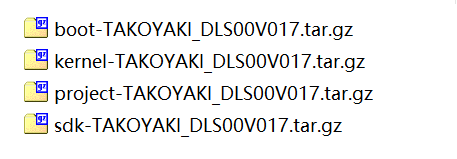
Figure 1-1 SDK Package
boot: Uboot source code
kernel: kernel source code, version: 4.9.84
project: For image compiling and making , including released header files and library.
SDK: For code testing.
2. Build The Compilation Environment
Developing and debugging by cross-compilation, that is the form of "host + target". The host and the target generally use serial port connection or network connection. As shown below.
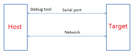
Figure2-1 Debug connection
Note: In addition to debugging, the debugtool can also read registers and burn empty flash through PC tools.
If you only need to debug, use the serial port device to correctly connect the debugging line sequence(con3), which should be consistent with the schematic diagram.
Debug Tool is required to read register or burn empty Flash, which need to purchase by yourself.
2.1. Install Linux
Recommended to use Ubuntu 16.04.
The installation process of lib and tool used in SDK compilation is as follows.
2.2. Install ubuntuserver
-
Install VMware Worksation.
-
Select the iso of 1604 and install it.
-
Click
Finishto complete the easy installation, the system will automatically complete the remaining steps. -
Install VMtools for copying, share the windows directory to ubuntu. Click here for reference.
The ubuntu installation is complete, then set up the development environment.
2.3. Install Lib And Tool
-
The first step to install ubuntu for the first time is to set the root password:
# sudo passwd, enter the password until the prompt is successful. -
Add
user accountwhen create virtual machine, personal accounts (such asbeal.wu) cannot be entered when creating ubuntu (the format error will be prompted), and the system will prompt that the account is illegal. After entering the system, use the command# sudo adduser beal.wu--forceto create it, When prompted to enter account information, just keep pressing Enter. -
After the account is created, install the relevant tools and compilation environment, execute the following commands:
# sudo apt-get

install libncurses5-dev

libncursesw5-dev
When prompted that
beal.wucannot execute sudoers, modify it as follows:sudo chmod u+w /etc/sudoers vi /etc/sudoers; reference root ALL=(ALL:ALL) ALL, add beal.wu ALL=(ALL:ALL) ALL
Then execute sudo to install, it is recommended to execute
#sudo apt-get updateafter installation. -
Install
sambato share linux files to windows.# sudo apt-get install samba samba-common # sudo smbpasswd -a beal.wu (add samba account for windows to access the linuxsamba directory) modify /etc/samba/smb.conf [beal.wu] path=/home/beal.wu public=yes writable=yes valid users=beal.wu available=yes browseable=yes guest ok = yes
After this, samba configuration is complete, restart samba, test access to samba from windows: \\192.168.1.11 (your ubuntu ip)
-
Install
sshfor login debugging.sudo apt-get install openssh-server; -
Some tools need to be installed for SDK compilation, or the compilation will fail.
# sudo apt-get install libc6-dev-i386
# sudo apt-get install lib32z1 lib32ncurses5
# sudo apt-get install libuuid1:i386
# sudo apt-get install cmake
# sudo apt-get install libncurses5-dev libncursesw5-dev
# sudo apt install bc
# sudo apt-get install xz-utils
# sudo apt-get install automake
# sudo apt-get install libtool
# sudo apt-get install libevdev-dev
# sudo apt-get install pkg-config
The above tool and lib are necessary and install all before compilation. You can try not to install first, and check related errors after compiling.
-
If the default is
sh, please change it tobash.Sudo rm /bin/sh Sudo ln –s /bin/bash /bin/sh
-
Install toolchain
-
Copy
gcc-arm-8.2-2018.08-x86_64-arm-linux-gnueabihf.tar.gzto/opt/directory -
Unzip toolchain
-
In order to avoid manual export every time, set the toolchain to the environment variable.
-
Add
export PATH=/opt/gcc-arm-8.2-2018.08-x86_64-arm-linux-gnueabihf/bin:$PATHin/etc/profile.
-
-
Execute compilation.
2.4. Install Cross Compilation Tool
We provide gcc-arm-8.2-2018.08-x86_64-arm-linux-gnueabihf to compile the glibc version.
Glibc:2.28
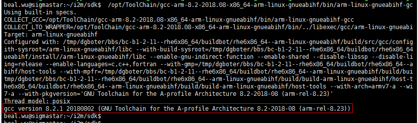
Figure2-2
3. Compile SDK
Takoyaki support two startup methods: nor flash and spi nand flash.
Different configuration files are used to distinguish the methods when compiling in SDK. SDK contains uboot and kernel sourcecode. Generate burnable images by packaging the script in the project.
Spinor and Spinand can work normally. Display demo board is equipped with Spinor flash, which can be layout by yourself. If the Display demo board needs to be changed to Spinand for debugging, please contact FAE.
3.1. Unzip Code
Obtain the SDK from FTP, the sourcecode format is as follows:
tar zxvf boot-TAKOYAKI_DLS00V017.tar.gz
…
tar zxvf sdk-TAKOYAKI_DLS00V017.tar.gz
3.2. Compile Boot
-
SPI-NOR package
#cd ${your path}/boot
#declare -x ARCH="arm"
#declare -x CROSS_COMPILE="arm-linux-gnueabihf-"
#make infinity2m_defconfig; //spinor
#make infinity2m_spinand_defconfig; //Spinand
#make menuconfig; //modify && save
#make clean;
#make
-
Get image
# cp u-boot.xz.img.bin ${ your_release_path } //spinor
# cp u-boot_spinand.xz.img.bin ${ your_release_path } //Spinand
3.3. Compile Kernel
-
Kernel
CHIP Glibc compiler Uclibc compiler Kernel make config Takoyaki spinor arm-linux-gnueabihf- NA infinity2m_ssc011a_s01a_minigui_defconfig Takoyaki spinand arm-linux-gnueabihf- NA infinity2m_spinand_ssc011a_s01a_minigui_defconfig Note: Please refer to the table and chip version to do the corresponding compilation.
# cd ${your path}/kernel
# declare -x ARCH="arm"
# declare -x CROSS_COMPILE=" arm-linux-gnueabihf-"
# make infinity2m_ssc011a_s01a_minigui_defconfig // Takoyaki spinor
# make infinity2m_spinand_ssc011a_s01a_minigui_defconfig // Takoyaki  Spinand
# make menuconfig; //modify && save
# make clean;
# make
-
Get image
//Takoyaki Spinand

# cp arch/arm/boot/uImage.xz   project\release\nvr\i2m\011A\glibc\8.2.1\bin\kernel\spinand

//Takoyaki spinor

# cp arch/arm/boot/uImage.xz   project\release\nvr\i2m\011A\glibc\8.2.
1\bin\kernel\nor
3.4. Compile SDK(ALKAID)
-
Build Sdk package
CHIP Glibc Uclibc QFN128 64M: SSD201 Nor nor.glibc-squashfs.011a.64 N/A QFN128 64M: SSD201 Nand spinand.glibc.011a.64 N/A QFN128 128M: SSD202D Nor nor.glibc-squashfs.011a.128 N/A QFN128 128M: SSD202D Nand spinand.glibc.011a.128 N/A Note: Please refer to the table and chip version to do the corresponding compilation.
# cd ${your path}/project
8.2.1:
Glibc:
# . /setup_config.sh ./configs/nvr/i2m/8.2.1/nor.glibc-squashfs.011a.64 // Takoyaki  Spinor
# . /setup_config.sh ./configs/nvr/i2m/8.2.1/spinand.glibc.011a.64 // Takoyaki  Spinand
# make clean; make image
-
Get image
# cd ${Alkaid}/project/image/output/images
Note:
If the
kernel kowas modified, release kernel before make image.cd /project/kbuild/4.9.84: ./release.sh -k kernel_path -b 011A -p nvr -f nor -c i2m -l glibc -v 8.2.1 //nor glibc ./release.sh -k kernel_path -b 011A -p nvr -f spinand -c i2m -l glibc -v 8.2.1 //spinand glibc
4. Burning
4.1. Burning code by uboot
-
Run tftp (FTP server) on PC
Step1. Use the tftp tool to point to the image path:
SDK\project\image\output\images\, and select the correct network adapter.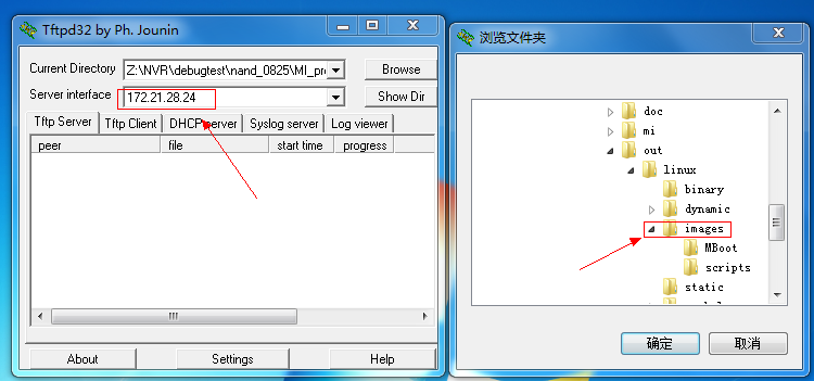
Figure4-1
Step 2. Correctly connect the board's network port and debug serial tool to PC.
-
Run tftp (FTP Client) on Demo Board
Step 1. Turn on the board, press and hold
Enterto enter boot loader command line.-
Please set the IP for the first burning(Unless the ip setting is changed or flash is replaced)
# setenv gatewayip 192.168.1.1
# setenv ipaddr 192.168.1.127           // Set the IP used by FTP Client (EVB)
# setenv netmask 255.255.255.0
# setenv serverip 192.168.1.100     //Set the IP used by FTP server(PC)
# saveenv
Note:
-
To ensure the successful burning, please set PC and development board in the same network segment.
-
Please use static allocate IP to prevent IP address jump during burning.
-
You can also use an independent network adapter to directly connect the PC to the development board, fix the LAN IP address and set the development board according to the above.
-
-
Execute the following command in UBOOT console to automatically burn by Ethernet.
# estar (OR: estar auto_update.txt, you can also burn one of the partitions)
-
4.2. Burning uboot by ISP Tool
Burn empty flash
It is suitable for empty burning, or where uboot is damaged and cann`t be upgraded through it.
-
SPI-NOR-Flash
-
Default Partition layout
Table4-1
No range size IPL 0x00000000-0x00010000 64KB IPL_CUST 0x00010000-0x00020000 64KB MXPT 0x00020000-0x00030000 64KB UBOOT 0x00030000-0x0004F000 124KB UBOOT_ENV 0x0004F000-0x00050000 4KB BOOT 0x00000000-0x00050000 256KB KERNEL 0x00050000-0x00250000 2048KB rootfs 0x00250000-0x00550000 3072KB nvrservice 0x00550000-0x009D0000 4800KB customer 0x009D0000-0x00F00000 5300KB The table is for reference only. Please refer to the following figure for partition information. The following code segment in
board/i2m/boot/nor/partition/tool/mxp_gen.cis partition information.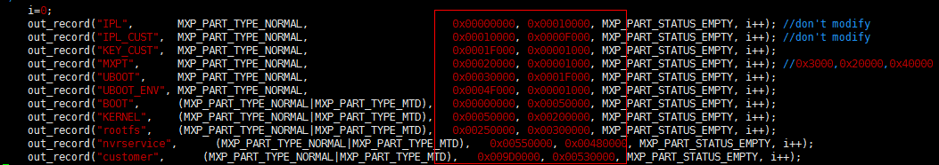
Figure4-2
The partition information that has been burned in the current flash can be viewed in uboot using the command below.
SigmaStar # mxp t.list -
Burning code by ISP tool
Table4-2
offset Binary storage directory IPL.bin 0x0000 ${ALKAID}\project\image\output\images\IPL.bin IPL_CUST.bin 0x10000 ${ALKAID}\project\image\output\images\IPL_CUST.bin MXP_SF.bin 0x20000 ${ALKAID}\project\image\output\images\MXP_SF.bin u-boot.xz.img.bin 0x30000 ${ALKAID}\project\image\output\images\u-boot.xz.img.bin -
Burning Steps
-
Step1. Execute ISP tool, and close UART terminal for normal connection.
Input
debugto close it in uboot or input11111in system.Note: Be sure to close the serial port connection.
-
Step2. Select SPI tab, and click
Moreto selectSPI.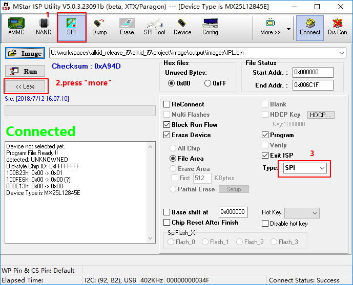
Figure4-3
-
Step3. Load the burned file and click
Connect.
Figure4-4
-
Step4. Load image
IPL.binand clickRun.Note: Be sure to select
erase file area.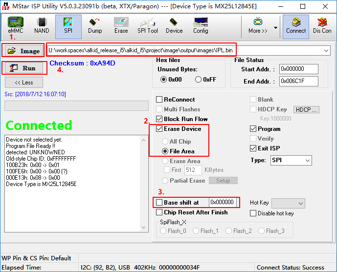
Figure4-5
-
Step5. Load image
IPL_CUST.binand cancelErase Device, setBase shiftat 0x10000.Note: This may change with the version. Refer to Table4-2 for the Base shift address.
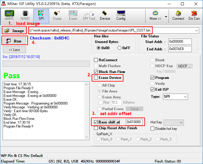
Figure4-6
-
Step6. Load image
MXP_SF.binand setBase shiftat 0x20000.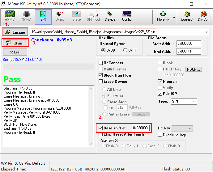
Figure4-7
-
Step7. Load image
u-boot.xz.img.binand setBase shiftat 0x30000.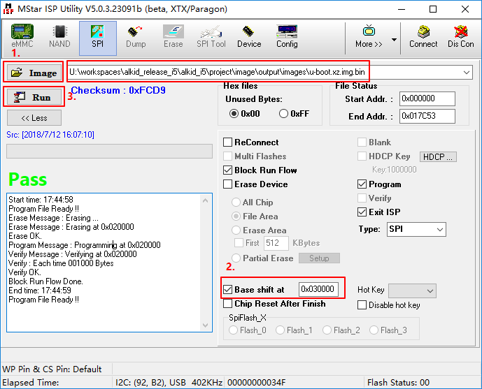
Figure4-8
-
Step8. Restart
Demo Boardand close the tool, then refer the section 4.1. Burning code by uboot.Enter Uboot and use the TFTP burning method to burn the remaining parts.
-
-
-
Spinand flash
The board connection and configurations are the same as Spinor, the difference is that spinand should be selected in the Flash type.
Select spinand in burning selection then connect.
Burn GCIS.bin:
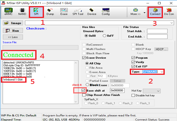
Figure4-9
Burn IPL.bin:
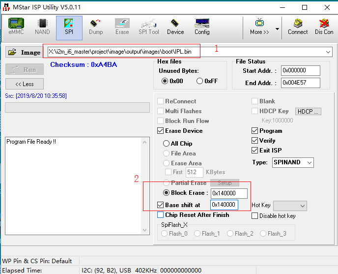
Figure4-10
Burn IPL_CUST.bin:

Figure4-11
Burn uboot:
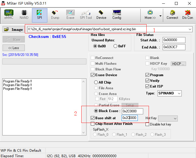
Figure4-12
Burning spinand is the same as spinor, only the address and file are slightly different.
Erase Device offset Image storage directory GCIS.bin All Chip 0x00000 yourPath/image IP.bin File Area 0x140000 yourPath/image IPL_CUST.bin File Area 0x200000 yourPath/image u-boot_spinand.xz.img.bin File Area 0x2C0000 yourPath/image After burning the above files, you can enter Uboot, and then use the network to burn other images.
Note: Stop serial port when burning, and close the serial port tool.
Stop the serial port in Uboot and input
debug.Stop the serial port in Kernel and input
11111.When the flash is empty, set the serial port baud to 38400, the result is not garbled, then the cpu is ok.
Execute
estarin uboot, use tftp to update image.
5. Memory Usage
The following table is about memory allocation. Memory has two parts: LX and Layout.
| composition | size | use | configurable or not | |
|---|---|---|---|---|
| LX | MMA | 21M(mabey changed) | Because some modules in the SDK (such as VDEC, VENC, etc.) require continuous physical memory, a piece of memory is reserved for them to allocate and is managed by MI_SYS | Y. Modified according to requirements, 1080P decoding display needs about 9M. |
| Linux mem | 44M | In addition to the reserved mma, the remaining memory of LX is managed by linux,the default value can be seen from /proc/meminfo is about 40M, the kernel text will reserve about 4M of memory (related to the kernel config, the larger the kernel, the more memory is reserved, so irrelevant configurations need to be deleted) / # cat /sys/kernel/debug/memblock/reserved 0: 0x20004000..0x20007fff 1: 0x20008240..0x203cfeb7 | Y | |
| LAYOUT | AI,AO, ect. | 1M | The memory is reserved for some necessary files, which also needs to be physically continuous, in order to prevent it from dividing the large memory, layout and fix its physical address | Y. 1M memory must be reserved. |
| total | 64M | |||
| Mem layout | /project/board/i2m/mmap/MMAP_I2M_64M.h Use SCA.exe tool to adjust | |||
| sz=0x1500000 in /project/configs/nvr/i2m/8.2.1/nor.glibc-squashfs.011a.64 | ||||
| cma is in meminfo total, add cma=2M in bootargs to configure | ||||
Previously, the memory of FB was layout in mmap.ini, because of being too flexible and frequently changing screen resolution, mmap.ini often needed to be re-layout. In order to solve this situation, now configure the memory allocation of FB to dynamically allocate from mma, which is compatible with the previous allocation method. Firstly, check whether the FB memory is configured from mmap.ini, and then check /config/fbdev.ini , finally according to the fbdev driver allocation.
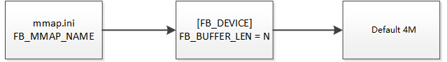
Figure5-1
6. MMAP Adjustment
6.1. mmap.ini
The built-in DDR2 capacity of the chip is 64M. We use mmap.ini as the memory configuration file, which contains the pre-allocated memory but not visible in the Linux management.
The /config/mmap.ini in the compiled image comes from /project/board/i2m/mmap, the header file in the specific project used needs to be viewed in /project/configs/nvr/i2m/8.2.1/nor .glibc-squashfs.011a.64.
Such as: MMAP = MMAP_I2M_64M.h
If the chip is SSD202, modify MMAP = MMAP_I2M_128M.h
Linux will analyze mmap.ini to initialize the memory, including the ai and ao of the mmap layout.
The path of reserved memory is # cat /sys/kernel/debug/memblock/reserved.
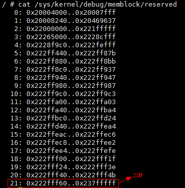
Figure6-1
6.2. mmap.ini Layout Adjustment
Open SCA.exe and load the configuration files, as shown below.
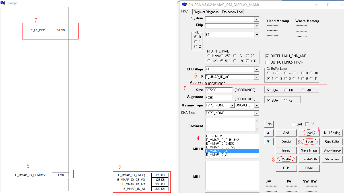
Figure6-2
-
Load the corresponding configuration files.
/project/board/i2m/mmap/ MMAP_I2M_64M.h -
Save the modification.
-
Select the corresponding layout and modify the size, click
modifyto finish edit. -
The currently edited layout memory in mmap.ini.
-
Size: the modify area, in which can select BYTE, KB and MB, input the corresponding capacity in the box.
-
The name of the currently selected layout block, it is editable, input a custom name in this area to add a new layout.
-
The length of LX in the current mmap.ini.
-
The current length of DUMMY in mmap.ini, DUMMY contains more small pieces of memory.
-
The memory less than 1M is attached to the dummy layout.